
Data Flow Diagrams
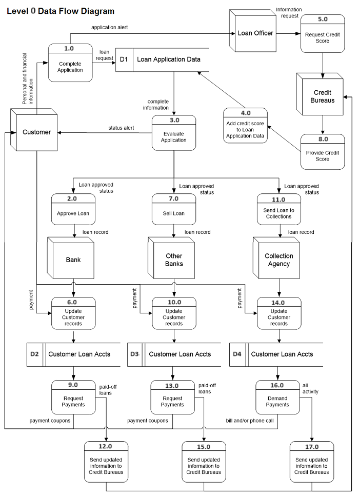
These are created to develop, analyze, and otherwise document whole systems. An overview of the system is called Context Level; including all major working parts constitute Level 0 diagrams. Child diagrams are where a small part of the system is explained in further detail. As with the other diagramming processes shown on these pages, there are specific rules to follow.
In a Level 0 diagram, processes are numbered 1.0, 2.0, etc. and assigned in a diagonal from top left to bottom right. Data stores are numbered D1, D2, etc., also assigned in a general top-left-to-bottom-right fashion. Entities are not numbered. Data stores cannot be connected to other data stores. If you are working on a school assignment, make sure you check the requirements in the instructions and read through DFDs in the textbook.
© 2008- Tamara Fudge